
AC motors instrumentation
Phase Angle Measurement Instrumentation, series 2000 includes networked voltage sensors, current sensors and transducers, and Phase Angle Diagnostics Controller.
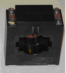
Current sensors
Current sensors are closed loop type current transformers, Fig 1. They have galvanic isolation from the primary to the secondary windings.
| Model | Rated current (A) | Rated output
(A) |
Accuracy
% |
Linearity
% |
Primary
Aperture (Inches) |
Mounting |
| CL 1 | 1 | 1 | 0.3 | 0.2 | 2 | Panel |
| CL 5 | 5 | 5 | 0.3 | 0.2 | 2 | Panel |
| CL 50 | 50 | 5 | 0.3 | 0.2 | 6 |
Panel |
| CL 100 | 100 | 5 | 0.3 | 0.2 | 6 | Panel |
| CL 250 | 250 | 5 | 0.3 | 0.2 | 6 |
Panel |
| CL 500 | 500 | 5 | 0.3 | 0.2 | 6 | Panel |
| CL 1000 | 1000 | 5 | 0.3 | 0.2 | 6 | Panel |
Fig 1
Shows the current measuring sensors, used to collect the motor current Sine.
The output of current transformers is 0-5A. The model of the transformer used depends on the motor current. The typical size of current transformers is 100 X 100 X 25 mm.
C/V Converters
Current-To-Voltage Converters, model C/V 2000, are shown in Figure 2,
This device transforms current signals 0-5A into voltage signals 0-5 V. The size of Current-To-Voltage Converters is 70 x 86 x 49 mm.
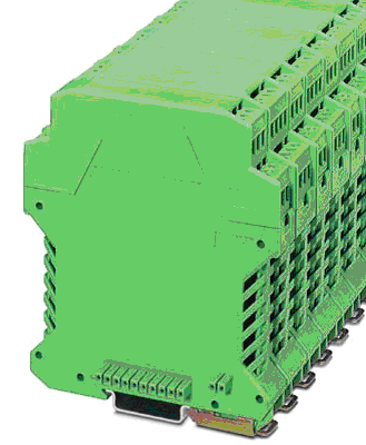
Current Transducers
These devices are three-phased. One device is needed for an induction motor. They perform the automatic synchronization of voltage and current signals related to different phases. Current transducers are networked. Only one wire connects the group of transducers with the Phase Angle Diagnostics Controller, PADC.
The current transducers can be installed inside an electrical cabinet or up to 50 meters from the cabinet
As shown in Figure 3, the current transducers are mounted on DIN rails.
The size of one current transducer is: 110 X 85 x 25 mm.
Voltage sensors
The number of voltage sensors depends on the number of power supply transformers used with monitored equipment. Voltage sensors can be located inside the electrical cabinet or up to 50 meters from the cabinet. The voltage sensors have the same enclosures as current transducers (Figure 3,). The voltage sensor is one-phase device. The phase transformer needs three voltage sensors. The voltage sensors connected to one or a number of power transformers. The voltage sensors are connected directly to the 480 V line. In the case of voltage higher then 480 V, voltage measurement transformers are used.
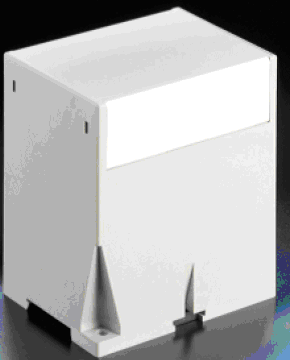
Phase Angle Diagnostics Controllers, PADC.
Phase Angle Diagnostic Controller, PADC, is shown on the Figure 4
PADC functions follow:
• PADC collects the analog signals from Voltage and Current sensors and builds the Phase angle pulses. The pulse front corresponds with the Voltage Sine zero crossing and back front with Current Sine zero crossing.
• PADC calculates the pulse width that is the phase angle value.
• PADC measures the voltage and current amplitudes values
• PADC stores the time series of voltage and current amplitudes and Phase Angle time series and prepares them for transmitting to the Embedded Server or Data Acquisition computer.
• PADC is connected by USB to the Embedded Server or Data Acquisition computer.
The size of PADC is 75 x 150 x 110 mm. It is DIN rails or shelf mounted.
The distances between C/V converters, current transducers, PADC and embedded computer is only two meters – meaning that all these devices are within two meters of each other.
The cables connected the current transformers and C/V converters can run through ducts along with the 480 Volt wiring.
Embedded computer specifications
Specifications:
Computer Platform
CPU: Socket 478, Pentium 4
Chipset : Intel ICH4
Memory: 512 Mb
PCI slots: 4 slots with PCI specification 2.2
USB1: 4 USB1 ports
I/O: 1 PS/2 mouse port, 1 PS/2 keyboard port, parallel port 4 Sequential ports
Hard disk: 60 Gb
Voltage Supply: 220/110V
Power: 300W
Size: 405 x 403 x 175
Data Acquisition:
Number of lines: 48, in 6x 8bits
Input logic low: 0.5 V o.8 V
Input logic high: 2V to 5V
Input load current +/- 10 microA max
Counter/Timers:
Number: 3 independent
Compatibility: TTL
Resolution: 16 bit
Input frequency: 8 MHz max
On-board clock: 2 MHz
Watchdog: Optional
PMCIA modem: Optional
Output relay: Optional
Environmental conditions:
Operation temperature: 0 – 55 C
Humidity: 95%